Profiles and steel structures
Why Z-sections are lapped and when the connection makes sense
In brief
On a hall roof, you can see Z-purlins overlapping above the supports. This is not a random surplus of material. In the designed arrangement, the lap helps transfer forces between successive sections. This allows cold-formed profiles to form purlins with a defined continuity. However, the benefits depend on the entire solution. Two profiles placed side by side do not automatically become one correctly functioning beam. The roof covering transfers load to the purlins, and the purlins transfer it to the main structure. The Z-section is one of the possible cross-sections for this element. It must carry actions resulting from, among other things, the weight of the roof, snow and wind. The purlin spacing also matters. The larger the roof area assigned to one purlin, the different the load the profile receives.
First, the load path must be established
Galvanised profiles work within a specific support arrangement. A beam supported on two supports behaves differently from an arrangement of several connected spans. The correctness of the lap therefore cannot be assessed from a photograph alone. It is necessary to know what force path was assumed in the calculations. Only this picture explains the location and role of the connection.
What the Z geometry enables
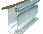
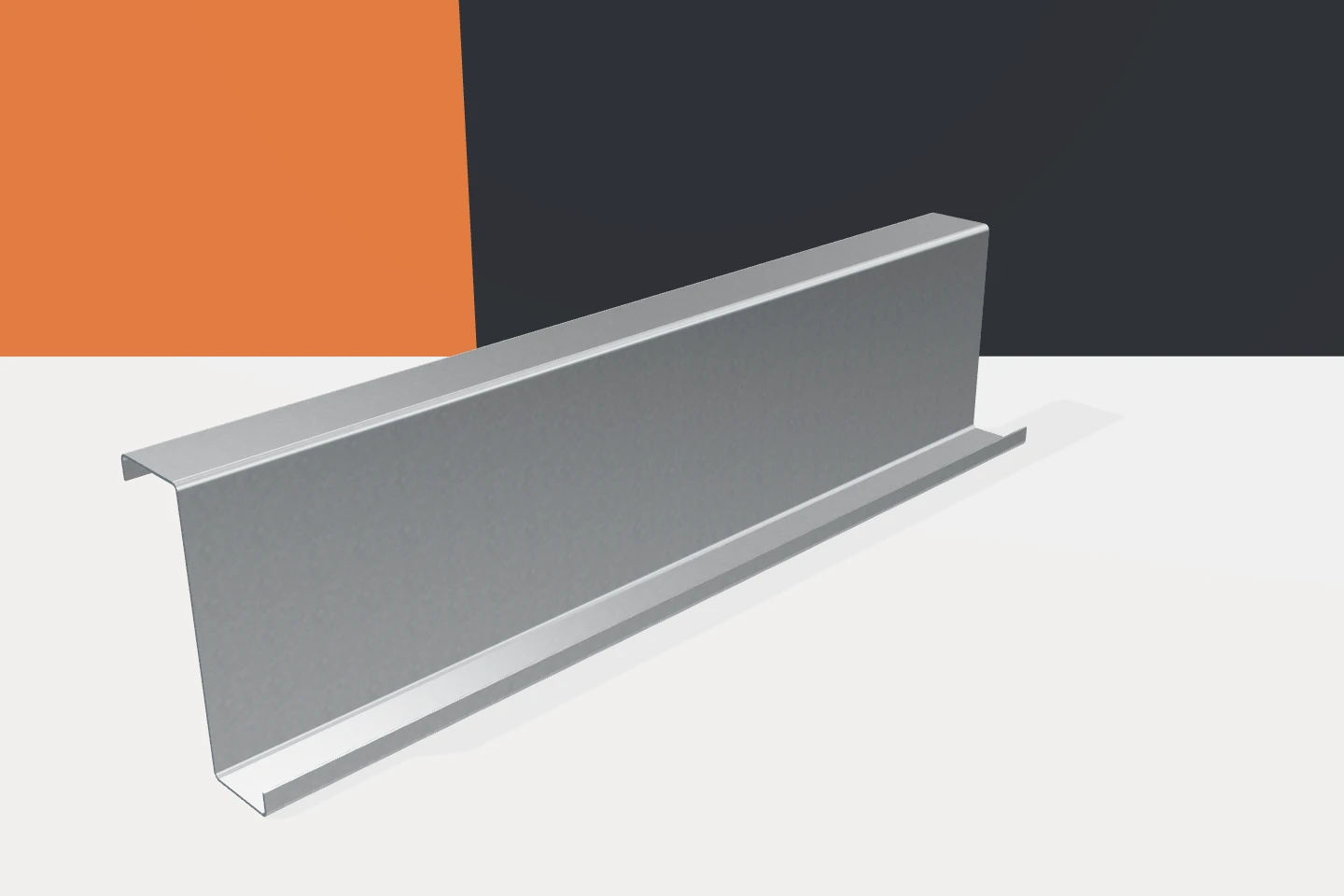
The flanges of the Z-profile face in opposite directions. In lap systems they have appropriately matched widths. This facilitates sliding one section into the other. In the region of the support, a segment with two elements is created. Its actual behaviour is determined by both the geometry and the bolted connection. Contact between the sheets alone is not sufficient to transfer all required forces.
Z-profiles from two different series may not fit together. The problem may be the flange width, the edge fold or the corner radius. Forced assembly leads to deformation. This is precisely why selecting a replacement requires checking the entire cross-section. Cold-formed profiles are not interchangeable solely on the basis of the height stated in the name.
An example of actual geometry helps to understand this difference. A Z-profile with a height of 200 mm and a thickness of 2 mm may have flanges 67 and 60 mm wide and 18.5 mm stiffening lips. These figures describe a specific variant. They are not universal dimensions for all Z-profiles with a height of 200 mm, nor are they information about their load-bearing capacity.
The lap length is not a universal number
The lap must cover the length specified for the given arrangement. Its length may depend on the span, loads, element thickness and the connection system adopted. Increasing this length on site does not always solve the problem. It changes the quantity of material, the hole layout and possible clashes. Shortening the lap without verification is equally unjustified.
Catalogues contain ready-made rules for specific systems. They should not be transferred directly to arbitrary galvanised profiles. A rule may take into account specific bolts, steel grade and the method of stabilisation. If any of these conditions changes, the solution must be checked again. This is not a formality but a condition for the connection’s conformity with the calculations.

The end span may require a different element
The end of the roof does not have the same conditions as its middle section. In multi-span systems, the design may specify different thicknesses or additional elements in the end spans. This also applies to the arrangement of laps and holes. Profiles of the same height may therefore have different assembly markings. They should not be swapped for the convenience of unloading.
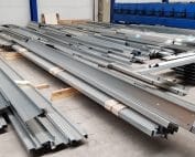
A well-prepared delivery distinguishes edge purlins, internal purlins and other variants. The markings should correspond to the roof plan. This simple organisation reduces mistakes. It also allows material to be used where it is needed. Standardising all Z-sections to the heaviest variant may simplify the list, but it is not necessarily economically justified.
Bolts and holes are part of the load-bearing system
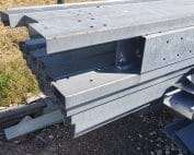
In a connection, the number of fasteners, their position and parameters matter. A hole too close to the edge can weaken the local area of the sheet. An additional hole made without agreement also changes the element. It is therefore worth preparing the holes in the factory according to the approved drawing. Installation is then more repeatable and requires less work at height.
Not every discrepancy can be removed by drilling out. First, the orientation of the profile, the part marking and the actual support spacing should be checked. The error may lie elsewhere than the hole. If the Z-sections do not fit, a technical decision is needed. Forcing the connection with a tool does not confirm that the design assumptions have been maintained.
The lap does not replace bracing
Cold-formed profiles have thin walls and open cross-sections. They require verification of stability, including torsional behaviour. A doubled section over a support does not solve all problems in the span. Bracing, restraints or other system elements may be needed. Their position results from the roof geometry and the load application.
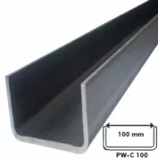
The covering also does not always provide the assumed lateral support. The influence of the steel sheet or sandwich panel must be confirmed for the fastenings used. This also applies to the condition before the roof is closed. Channels, sigma profiles and omegas have their own stabilisation requirements. No cross-section name exempts from the assessment of the entire structure.
When to consider a different arrangement
The lap arrangement is one possibility. Separate sections or solutions with cover plates are also used. The choice is determined by the static conditions, the number of spans and the organisation of work. Laps can increase the number of screws and the installation time. On the other hand, a suitably selected system allows material to be arranged favourably. The balance must be carried out for the specific hall.
When ordering, a complete schedule should be provided, not just the metreage of Z-sections. The schedule should include all profile variants, fasteners and bracing. Then the galvanised profiles form a clear system. The value of the solution results from predictable behaviour and efficient installation. It does not result from the mere fact that two pieces of steel overlap.
7 branches. Materials closer to your project.
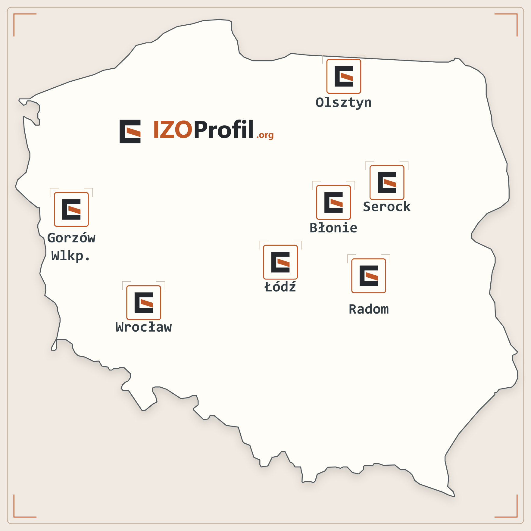
- SEROCK — Dzierżenin 34 E
- BŁONIE — ul. Sochaczewska 138A
- RADOM — ul. Grobickiego 8
- ŁÓDŹ — Natolin 8
- OLSZTYN — Barczewo, ul. Prosta 9
- WROCŁAW — ul. Jerzmanowska 10C
- GORZÓW WLKP. — ul. Zielona 33/34