Metal roofing
Lighting and speakers beneath a grandstand roof: preparing an equipment plan
At a glance
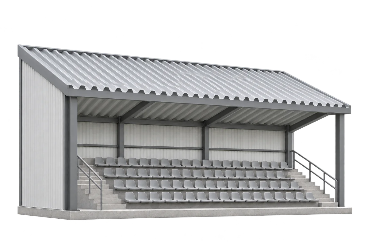
A grandstand roof may carry lights, speakers, cameras and cable routes. Before an installer proposes fixing them to profiled sheeting or the supporting frame, prepare a shared equipment plan. Connect each device location to its specification, cable route and future servicing arrangements. The speaker weight alone does not describe the complete installation: brackets and other suspension components also need to be identified. This guide explains how to assemble information for the venue operator, designers and contractors. It also separates suggested positions from approved fixing locations and sets out a practical handover record. The support and connection must be selected through a design that accounts for the actual roof.
Give every device a reference
Mark lights and speakers separately on the seating plan, for example L01 and S01, and give each a schedule entry. Update the same entry when its position changes. A discussion about “the speaker near the entrance” can then refer to one identifiable proposal rather than several competing layouts.
Collect data for the complete assembly
Attach the device datasheet, dimensions and weight. List the bracket, extension arm and other assembly components separately. Include manufacturer restrictions on mounting or outdoor use with the proposal. Mark figures taken from a similar model as unconfirmed rather than transferring them into the purchase specification.
Show where the device sits relative to the proposed support and indicate its orientation. The structural engineer may also need information about wind exposure and operating effects. Avoid reducing the review to a single weight figure; ask the designers to identify any additional data required.
Identify the proposed fixing substrate
Add structural member references from the roof drawings to a photograph of its underside. State whether the proposal concerns a purlin, another frame member or the profiled sheet itself. Each calls for an appropriate connection detail. An existing roof screw does not establish that equipment can be suspended there.
An additional load that was not included in the roof design needs the structural designer’s approval. The approved detail should identify the location, supported component and connection. If the actual substrate differs from the drawing, hold that installation item until the discrepancy has been resolved.
Bring the discipline drawings together
Overlay equipment locations, cable routes and roof flashing extents. Flag any proposed roof penetration and refer it to the roofing contractor and services designers before an opening is made. Give each penetration detail a named coordinator in the schedule so that its resolution can be tracked.
Keep one clash register with drawing references and response dates. A speaker might obstruct an inspection opening, while a cable route could cross a planned flashing detail. Close an entry by referencing the revised drawing, giving the installation team a usable record of the agreed change.
Plan servicing access
For each item, note the inspection, adjustment or replacement activities specified in its instructions. Agree access arrangements and the seating areas that would need to be closed during servicing with the contractor and venue operator. This helps assess the proposed location before brackets are ordered.
Allow for removing the device from its bracket and reaching its connectors. Retain a drawing or photograph showing the required space. When the installation is expanded later, this record makes it easier to check whether a new cable or light obstructs the agreed servicing access.
Close out approvals before installation
Before work starts, mark each equipment entry as approved, awaiting information or rejected. Issue the correct drawing revision and the designers’ requirements for installation. A clear status list reduces the chance of an earlier concept sketch being mistaken for a construction instruction.
At handover, record the installed locations, device references and acceptance date. Retain approved details and the change log. If the operator later proposes a heavier speaker or an additional camera, the next review can start from a documented description of the existing installation.
7 branches. Materials closer to your project.
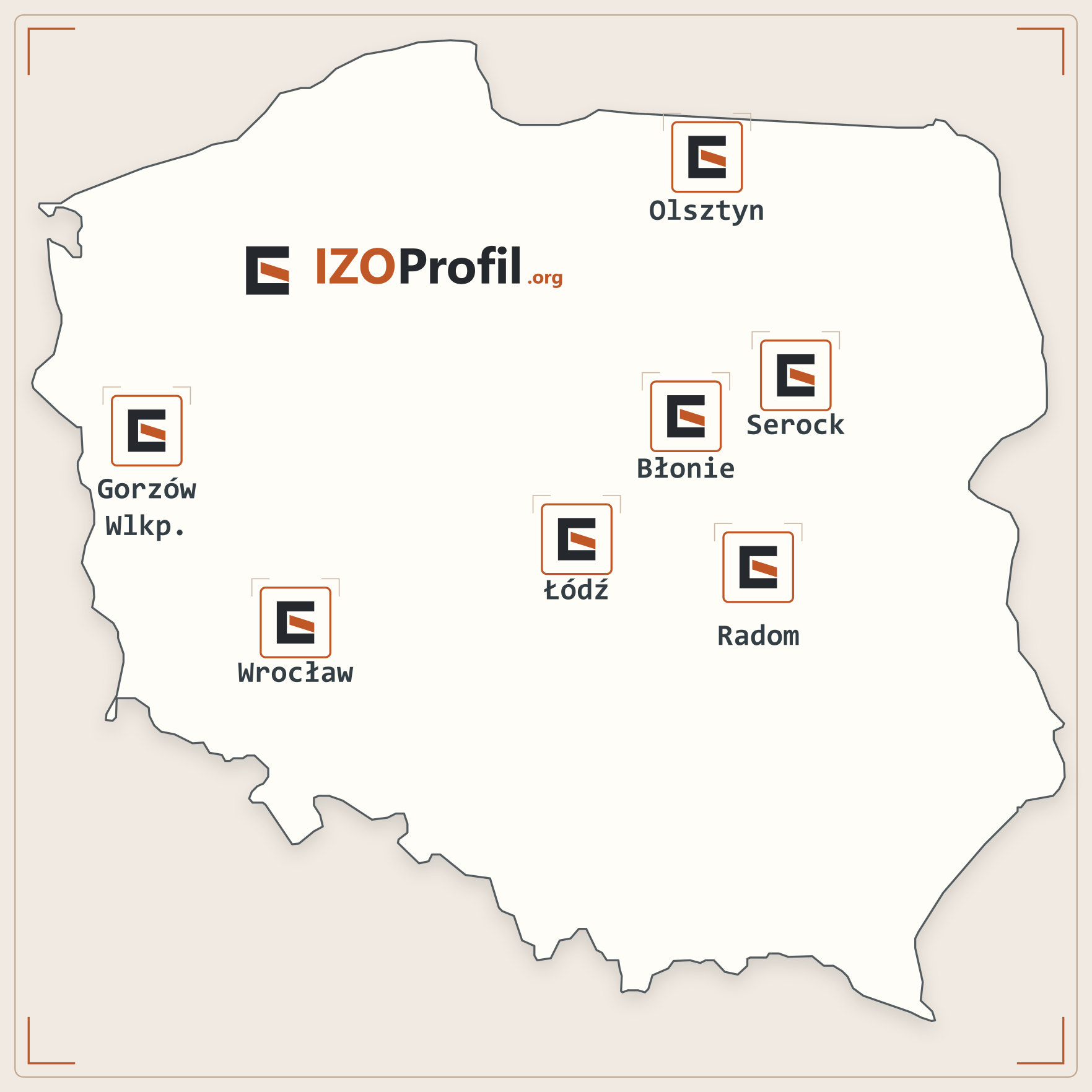
- SEROCK — Dzierżenin 34 E
- BŁONIE — ul. Sochaczewska 138A
- RADOM — ul. Grobickiego 8
- ŁÓDŹ — Natolin 8
- OLSZTYN — Barczewo, ul. Prosta 9
- WROCŁAW — ul. Jerzmanowska 10C
- GORZÓW WLKP. — ul. Zielona 33/34