PIR insulation
IKO enertherm ALU TG: joints, gaps and airtightness of the building element
At a glance
With IKO enertherm ALU TG, a gap first requires establishing whether it has arisen at the factory tongue-and-groove joint or at a cut piece without a tongue. These are two different mechanisms: damage to the profile during processing, or the result of a cut which by definition changes the edge. The inspection should cover the width of the last strip, the position of the profiled-edge ends and the conditions under which the symptom appeared. A row plan with the cut edges marked provides a reference for the assessment. Only against this background can a joint defect be distinguished from a characteristic of the cut piece and the scope of the repair be specified.

First, the question of the cause
A cutting plan drawing with post-cut edges shows whether the design provided for continuity of the layer at the cut pieces. Comparing against it reveals whether the gap results from the cutting geometry or from incorrect execution of the joint. Without this reference, a factory feature of the board is sometimes taken as proof of an error.
The product in question and the scope of its data
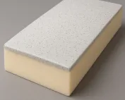
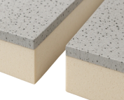
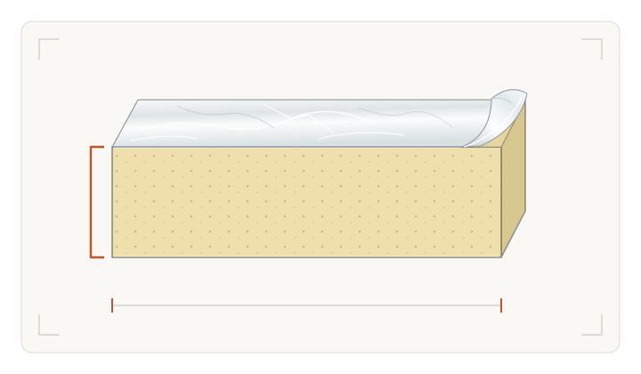
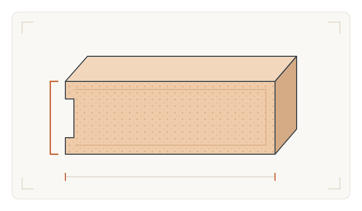
In IKO enertherm ALU TG, the rigid PIR foam core is enclosed by aluminium facings, and the edge has a factory tongue-and-groove profile. For this variant, the declared thermal conductivity is 0.022 W/(m·K), and the compressive strength is at least 175 kPa. The reaction to fire is F, while B-s2,d0 refers to a specific end use. The tongue-and-groove alone does not act as a structural connection or replace waterproofing. Cutting the board removes the factory shape of the edge, which is why the full product name is needed when checking an order, and the generic term polyurethane boards will not replace it.
How to read a simple example
When assessing an open gap, it is worth comparing three situations. In the first, both sheets have retained the factory profile but have not been properly pushed together. In the second, the tongue has been broken off during handling. In the third, the straight edge is the result of a planned cut at the perimeter. The mere appearance of a light strip between the boards does not determine which situation has occurred. The geometry must be inspected and related to the termination detail. Repairing a damaged element may require a different decision from executing a correct joint at a cut piece. The type of joint is therefore not determined solely by the TG label on an adjacent full board.
The example of IKO enertherm ALU TG shows that a description of the tongue-and-groove profile does not explain every gap. The background is the loss of the factory shape of the edges after cutting. Indicate on the drawing the places where the profile has disappeared. The description of fitting the tongue into the groove and sealing the perimeter serves as comparative material; where it deviates from the actual condition, correct the description of the board and layers first.
Matching the action to the identified problem
Changing the width of the first ALU TG row can improve the width of the final cut; an alternative is a full first row and a separate perimeter solution. Neither variant restores the factory tongue on the cut side. The laying coordinator should indicate on the cutting plan the installation direction and the termination detail matched to the actual edges.
What can be seen at the joint
The inspection of IKO enertherm ALU TG checks whether the edges of the tongue and groove are intact and matched and what condition the aluminium laminate of the ALU TG variant is in. A different print or colour is not the same as an open gap, a missing facing or permanent deformation. The reference is the description of the tongue-and-groove fit and the perimeter sealing. On the other side lies, or is to be created, a finish laid after acceptance of the joints, which may hinder access to the damage. Record whether the inspection covered the cut edge without a factory tongue or whether the cut side remained under the finish.
How to separate a feature from a defect
The ALU TG tongue should not be forced in to compensate for an uneven substrate. First check the bearing plane, then the edges left after cutting and their position in the rows. A joint assessment of the exposed area and the cutting plan will allow the coordinator to identify the cause of the tongue-and-groove mismatch.
The conclusion should have limits
On the ALU TG repair drawing, mark the sides that have lost their tongue or groove and how the insulation is to be closed at the perimeter. Distinguish findings concerning covered joints from joints inspected directly. The order should correspond to the cutting plan of full boards and cut pieces, together with their laying direction.
7 branches. Materials closer to your project.
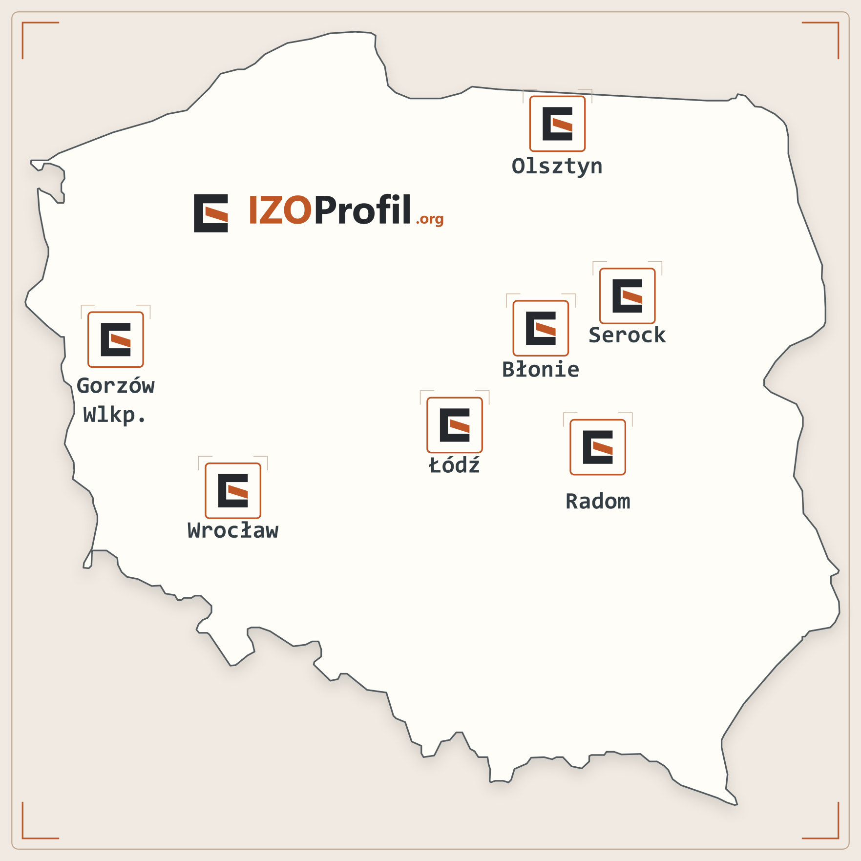
- SEROCK — Dzierżenin 34 E
- BŁONIE — ul. Sochaczewska 138A
- RADOM — ul. Grobickiego 8
- ŁÓDŹ — Natolin 8
- OLSZTYN — Barczewo, ul. Prosta 9
- WROCŁAW — ul. Jerzmanowska 10C
- GORZÓW WLKP. — ul. Zielona 33/34