PIR insulation
Does CS(10) show how much load a PIR-insulated floor can bear?
At a glance
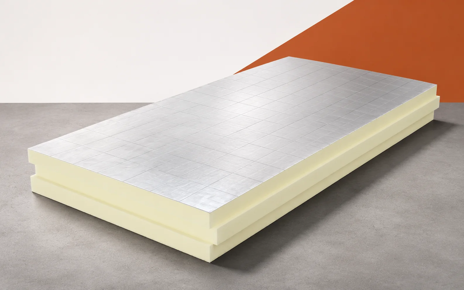
The number given for the compression of the board is not the finished load-bearing capacity of the floor. Assessing it requires the duration of loading, the pressure area and the construction of the substrate. PIR boards can perform well beneath a floor finish when the selection covers these relationships and the actual pattern of use. PIR boards are useful in a floor where the available height is limited. Low thermal conductivity allows an effective insulation layer to fit beneath the screed. A cold floor does not always indicate insulation that is too thin. The floor edges, the type of heating and the finishing layer may all be significant. The temperature of the finish depends on the conditions on both sides of the floor and on how the heating operates. The sensation of cold may differ between floor coverings even at a similar temperature.
The space beneath the floor
This is not a direct measurement of the insulation’s resistance. It is also worth checking the junction at the external wall. Only by reconstructing the cross-section and the conditions of use can it be assessed whether the PIR is of insufficient thickness.
What CS really means
CS(10) is the stress measured at a defined deformation of the specimen in a compression test, not the permissible load for a floor over its entire service life. The deformation itself is part of the definition of the parameter, so the value in the data sheet does not yet answer the question of the load-bearing capacity of the finished system.
It does not mean that such a large displacement can be accepted in the finished floor. The CS test uses a defined deformation to describe the behaviour of the specimen. The finished floor may require much smaller displacements in order to preserve the function of the screed and the finish. The test point should therefore not be treated as a recommended service condition. Data specific to the loads and their duration are needed. This difference explains why a rigid board still requires the whole system to be designed.
Support and load distribution
Continuous bearing beneath a board depends on the substrate being level. Either a raised area or a void under the insulation alters the load path. If a crack lies above such a void, the support beneath the board needs to be assessed.
High PIR hardness does not compensate for every error in substrate preparation. Cracking may be related to support, screed shrinkage, expansion joints or loading. The mere fact that PIR was used does not point to a single cause. It is worth reconstructing the installation location and the sequence of layers beneath the damage. If a void remained beneath the board, its behaviour may have differed from what was assumed. The repair should be matched to the identified mechanism instead of automatically replacing the insulation with another type.
Interaction with underfloor heating
Thermal insulation in a floor with heating limits heat loss to the cooler substrate, but does not determine the system output or the flow temperature. If the surface heats unevenly, the cause may lie in how the circuits are operating, so the assessment of the insulation layer must be set against the condition of the system.
Before blaming the insulation, it is also worth checking the system and the conditions under which it is controlled. A varying surface temperature may correspond to the pipe layout and the control of the circuits. The commissioning stage, the settings and the type of covering must be taken into account. The insulation beneath the system is responsible for limiting downward heat flow, but does not control the distribution of heat between the loops. The building assessment should be coordinated with the system assessment. This helps avoid dismantling a correct floor because of a fault in the controls.
Moisture and impact sound
The low water absorption of a particular PIR does not remove the need to protect against water from the ground or from a wet room; the position of the damp-proof layer follows from the design of the whole floor. The transmission of footstep noise to the wall may, however, indicate a rigid edge connection.
A change in the material’s lambda does not explain or eliminate such an acoustic bridge. The transmission of impact sound depends on the separation of the screed and its contact with the surroundings. A rigid connection at the wall can be significant despite a correct layer in the middle. It is worth checking the edges and the points where services pass through. The PIR thermal parameter is not used to assess this phenomenon. Separating the two functions helps in choosing an acoustic repair without assigning the material an inappropriate role.
Selecting the board for the room’s function
Answering the question about the load-bearing capacity of a PIR floor begins with establishing how the room will be used. A residential room is assessed differently from a technical room, and differently again from a storage area. With permanent heavy equipment, different data are needed than with short-term movement of people, which is why the board’s compression parameter alone does not determine the suitability of the system.
Identifying the load is the first step towards a proper assessment of the floor. A heavy wardrobe, partition or support can load the floor in different ways. Information is needed on the contact area and the duration of action. It is not enough to add up the mass of the equipment in the whole room. The assessment must be combined with the construction of the layer above the insulation. Such data make it possible to answer the question of safe use far more accurately than the compression value in the board’s data sheet alone.
Example of pressure and deformation
For orientation: a force of 2.5 kN on 0.01 m² corresponds to an average stress of about 250 kPa, and on a surface ten times larger – ten times lower. This is merely an illustrative calculation, without the distribution of forces in the screed, so it does not determine the permissible load on PIR. If 10% deformation were related to a 120 mm board, this would give a 12 mm change in thickness – which shows how the CS test point differs from the requirements of a finished floor. That is why, under a floor, the specific product and its mechanical data matter: polyurethane insulation can reduce the thickness of the section, but it does not take over the role of a layer distributing the pressure, and the polyurethane foam in the core is not a finished floor.
7 branches. Materials closer to your project.

- SEROCK — Dzierżenin 34 E
- BŁONIE — ul. Sochaczewska 138A
- RADOM — ul. Grobickiego 8
- ŁÓDŹ — Natolin 8
- OLSZTYN — Barczewo, ul. Prosta 9
- WROCŁAW — ul. Jerzmanowska 10C
- GORZÓW WLKP. — ul. Zielona 33/34