Insulation materials
How quickly can you prepare correct thermal and moisture calculations for a wall?
In brief
A quick result is only valid if the input data are correct. When selecting insulation, you need to know the wall layers, their condition and the conditions of use. A simple calculator helps compare thicknesses. However, it does not replace the assessment of moisture, thermal bridges and details. Particular care is needed with internal insulation. Prepare the layer build-up from the inside to the outside. Record their thicknesses and thermal properties. For an existing wall, the material must be identified accurately. The information “brick” alone is often too general. Include renders, gaps and existing insulation. Do not replace unknown data with the most favourable value from a catalogue.
What needs to be collected before starting the calculations?
Specify the indoor temperature and humidity and the external conditions separately. A studio heated continuously does not behave like a room used once a week. Moisture sources and ventilation matter. If the wall is damp, the cause must be established. A dry-masonry model will not explain the effects of a leak.
How do you calculate the resistance of a new layer?
For a homogeneous layer, R = d/λ applies. The thickness d is given in metres and λ in W/(m·K). For example, 80 mm of insulation with a λ of 0,022 gives an R of approximately 3,64 m²·K/W. This is the result for the layer alone. It is not the wall’s U-value nor a guarantee of achieving the required surface temperature.
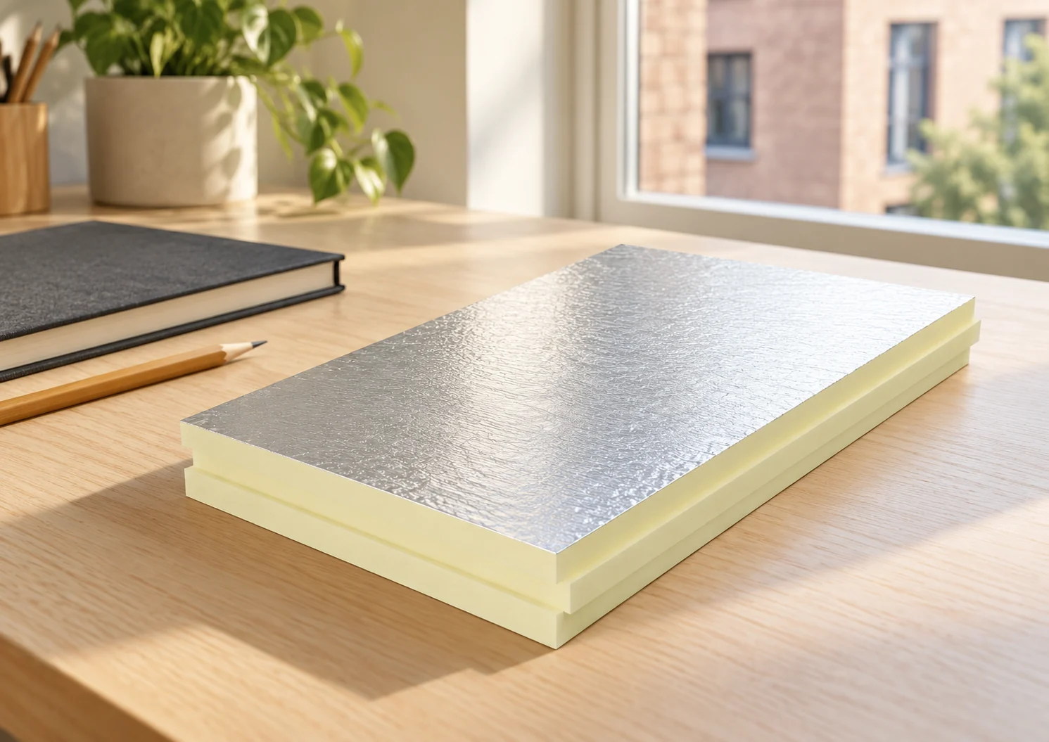
For a different type of facing or thickness range, the declared λ may differ. The value must be assigned to the selected product. A PIR board in foil and a board with a fleece backing intended for a specific system may have different parameters. One lowest figure should not be used for all variants.
Check the sensitivity of the result to changes in the data. For 80 mm of material with a λ of 0,026, the resistance is approximately 3,08, not 3,64. The difference does not arise from a calculator error but from a different product property. Assuming a nominal wall thickness without checking its actual construction works the same way. It is therefore worth keeping both variants until the materials are confirmed.
How do you go from R to the U-value?
In a simple model, the resistances of the layers and the surface heat transfer resistances are added together. The reciprocal of the sum gives the base U-value. The relevant corrections are then applied. Assume, purely as an example, that the remaining part of the building element has a total R = 1,10. Adding the layer with R = 3,64 gives a U of approximately 0,211 W/(m²·K).
This is a calculation for the assumed data, without a full assessment of a specific wall. Fasteners, repeated structural elements and thermal bridges can change the result. The figure must not be rounded down simply to reach the intended threshold. If the margin is small, the assumptions and corrections must be checked carefully.

What does the thermal result alone not resolve?
A low U-value does not prove the absence of moisture risk. An assessment of temperatures and moisture transport within the building element is needed. Simplified methods have their own assumptions and limitations. They may not adequately cover precipitation, rising damp, capillary transport or variable conditions over time.
With internal insulation, the existing masonry becomes cooler. Its ability to dry out changes. Beam ends, corners and reveals require separate attention. In difficult cases, a more detailed analysis is needed. A printout from a simple calculator should not be treated as full confirmation of the safety of the solution.
How do you check for thermal bridges and air leaks?
Calculating a single flat field does not describe the wall-to-floor junction. At such a point, heat flows in more than one direction. A two- or three-dimensional model may be needed. Heat losses and surface temperature are assessed. The latter information helps identify the risk of local cooling.
A leaky layer on the interior side can allow moist air to flow behind the insulation. A favourable λ of the material does not remedy this. Continuity of seals at the floor, ceiling and services must be designed. How the detail is executed is just as important as the number in the calculation table.
What should a useful report contain?
Record the input data, method, boundary conditions and result for each variant. Separate information confirmed from assumptions requiring verification on site. The report should also indicate the limitations of the model used. This allows another person to reproduce the calculations and assess whether the comparison is meaningful.
For a series of similar pavilions, a template can be used. However, dimensions, openings, usage conditions and location must be updated each time. Copying the result alone is risky. The finished document is meant to support a specific project, not merely to look like a complete set of calculations.
What else is worth asking about
Is a spreadsheet sufficient for preliminary selection?
It can help compare layer resistances and base U-values. However, the data must be selected correctly, and thermal bridges, moisture and the requirements of the entire building element must be assessed separately.
Does every wall require an equally complex analysis?
The scope depends on the construction and operating conditions. An old masonry wall with moisture and beams embedded in the wall requires different attention than a simple, well-recognised new partition.
7 branches. Materials closer to your project.

- SEROCK — Dzierżenin 34 E
- BŁONIE — ul. Sochaczewska 138A
- RADOM — ul. Grobickiego 8
- ŁÓDŹ — Natolin 8
- OLSZTYN — Barczewo, ul. Prosta 9
- WROCŁAW — ul. Jerzmanowska 10C
- GORZÓW WLKP. — ul. Zielona 33/34